WARNING: This information is outdated, but still provides some valuable insight to flying the DC-3 in a simulator. This page is more for nostalgic purposes. A large amount of the mentioned add-ons are no longer available.
 The
only sure way to increase your enjoyment of flying the DC-3 is to become
more proficient. And that's just what will happen if you work your way
through the following sections.
Nine sections cover the pre-takeoff to landing procedures as well as slow
flight and go-arounds. You'll learn and use those procedures in a
thirty-minute flight from Newport State, R.I. to Provincetown, Mass.
You'll love the 15-minute flight chosen to practice go around and
short-field landing techniques and full details are in the Go-Around
section. Fly from Quonset Airport, in North Kingstown, Rhode Island to
Elizabeth Field on Fishers Island, N.Y. If your approach to Elizabeth
Field's 1790 ft Runway 25 isn't perfect, you'll have to exercise a
go-around.
The
only sure way to increase your enjoyment of flying the DC-3 is to become
more proficient. And that's just what will happen if you work your way
through the following sections.
Nine sections cover the pre-takeoff to landing procedures as well as slow
flight and go-arounds. You'll learn and use those procedures in a
thirty-minute flight from Newport State, R.I. to Provincetown, Mass.
You'll love the 15-minute flight chosen to practice go around and
short-field landing techniques and full details are in the Go-Around
section. Fly from Quonset Airport, in North Kingstown, Rhode Island to
Elizabeth Field on Fishers Island, N.Y. If your approach to Elizabeth
Field's 1790 ft Runway 25 isn't perfect, you'll have to exercise a
go-around. We've chosen another airport for the short-field takeoff. It's Myricks Airport near Berkley, Mass., with a 2150 ft. turf runway. Should be a piece of cake with the right technique. See the Takeoff section for details.
The Sperry Autopilot, Fun Flights, and Checklists wrap up this chapter.
The DC-3, like all aircraft, should be "flown by the numbers." To get from one airport to another the pilot must takeoff at the proper speed, climb and descend at established rates and airspeeds, maintain desired headings and altitudes, navigate from one airport to another, perhaps perform an instrument approach to an airport, and land in a variety of wind and runway-surface conditions.
A typical flight has seven segments:
- Pre-Takeoff
- Takeoff.
- Climb.
- Cruise
- Descent.
- Approach.
- Landing.
On occasion you'll also encounter two other flight situations:
- The Go Around
- Slow flight.
While everyone has their favorite DC-3 aircraft and panel, Certain panel-aircraft combinations are required for the type-rating flights. These are noted after clicking the "New Pilots Enter Here" menu button. The various panel options are shown below for FS2004 back to FS98. Large-size instruments are on the panels so that you can quickly discern the effects of the flight and power controls. For best quality, video card and monitor permitting, set your Flight Simulator resolution to 1024 x 768 pixels or higher.
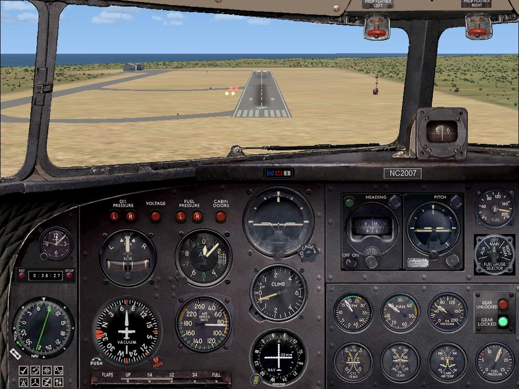
Several of the items on the Instrument Panel are worth noting.
Radio Magnetic Indicator
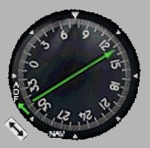 The
gauge on the lower left of the panel is a single-needle Radio Magnetic
Indicator, the RMI. This gauge is used for ADF navigation. It derives its
name from the fact that it indicates both the magnetic heading of the
aircraft and the magnetic bearing to a station. Its compass card rotates with the directional gyro and
so it
accurately
indicates the heading of the aircraft even when in turns. The RMI needle
always points to the low frequency beacon tuned in by the ADF receiver. The
aircraft's nose is straight up on all ADF gauges.
The
gauge on the lower left of the panel is a single-needle Radio Magnetic
Indicator, the RMI. This gauge is used for ADF navigation. It derives its
name from the fact that it indicates both the magnetic heading of the
aircraft and the magnetic bearing to a station. Its compass card rotates with the directional gyro and
so it
accurately
indicates the heading of the aircraft even when in turns. The RMI needle
always points to the low frequency beacon tuned in by the ADF receiver. The
aircraft's nose is straight up on all ADF gauges.
The RMI greatly simplifies ADF navigation since the needle indicates the
magnetic bearing to the station, and hence the pilot need only turn the
aircraft that heading to home to the beacon—not always, though. Go to the
Navigation Tutorial, courtesy of DC-3
Airways
Founder Charles Wood, to learn about that plus a lot of other really neat
stuff that you can do when flying the ADF.
This ADF indicator shows an aircraft on a 076° heading with a 134° magnetic
bearing to the beacon. This particular RMI gauge also digitally displays the
bearing to the beacon, which further simplifies navigation. When the ADF
receiver is off or the beacon is out of range, three dots appear in the
digital window and the indicator's arrow points directly to the right.
Sperry Autopilot
 A
second "gauge" that may be unfamiliar is the Sperry "Gyropilot." The
Gyropilot was the earliest commercial autopilot and considerably relieved
the pilot's task of maintaining heading and altitude, although acceptance by
early airline pilots was slow.
A
second "gauge" that may be unfamiliar is the Sperry "Gyropilot." The
Gyropilot was the earliest commercial autopilot and considerably relieved
the pilot's task of maintaining heading and altitude, although acceptance by
early airline pilots was slow.
The Sperry has fewer functions than its more-modern counterparts. For
example, it will not hold a specified altitude nor couple to the Instrument
Landing System, the ILS. But with it, a pilot can very acceptably maintain
the localizer heading and glide-slope rate of descent. It's kinda fun having
some control over that. Makes you feel more like the pilot.
A later section describes the Sperry setup and operation.
Digital Timer
 Pilots
should be wary when placing a timer on a panel. Many do not function
properly in all situations. The timer on our DC-3, also designed by Ike
Slack, works properly in every respect: It times correctly while flying,
pauses when the Flight Simulator is paused, and continues to time properly
in the various view modes. Start and stop the timer with the ST/SP button
and after it is stopped, reset it with the RST button. It displays hours,
minutes, and seconds.
Pilots
should be wary when placing a timer on a panel. Many do not function
properly in all situations. The timer on our DC-3, also designed by Ike
Slack, works properly in every respect: It times correctly while flying,
pauses when the Flight Simulator is paused, and continues to time properly
in the various view modes. Start and stop the timer with the ST/SP button
and after it is stopped, reset it with the RST button. It displays hours,
minutes, and seconds.
Use it to time your flights and critical legs of instrument approaches, and
as a reminder of when to begin your descent.
Once you begin using this instrument, you'll mount it on every panel, it's
that useful. Since you have no copilot, this modern nicety can reduce your
workload and eliminate much mental arithmetic.
Radio Stack
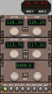 The
default "coffee-grinder" radios in the FS DC-3 were replaced by a digital
stack. Note that standby frequencies can be set in, allowing for quicker
frequency changes. Pop-up the Radio Stack by clicking the Radio Simicon,
idntifiable by its radio-tower image on it.
The
default "coffee-grinder" radios in the FS DC-3 were replaced by a digital
stack. Note that standby frequencies can be set in, allowing for quicker
frequency changes. Pop-up the Radio Stack by clicking the Radio Simicon,
idntifiable by its radio-tower image on it.
Click the radio knobs to change the frequencies up or down. Also click the
"ID" button on the radio panels to hear the Morse identifier of the
actively-tuned navaids.
On the Audio Panel at the bottom of the stack, the Audio Switch must be ON
for each receiver that you expect to listen to.
Be certain to place the DME, at the top of the stack, in the Nav-1 position
to display the distance to the Nav 1 station. Only Nav 1 is available on
this training panel.
Digital Readouts
 The
GPS gauge has been removed from the training DC-3 since it was not available
in the era of the DC-3. Note in the image to the left that the GPS Simicon
has been replaced with one labeled "DIG." Clicking this Simicon will display
digital readouts adjacent to the RMI and adjacent to VOR-1 for its OBS
setting. You will find these digital displays helpful during the type-rating
flights.
The
GPS gauge has been removed from the training DC-3 since it was not available
in the era of the DC-3. Note in the image to the left that the GPS Simicon
has been replaced with one labeled "DIG." Clicking this Simicon will display
digital readouts adjacent to the RMI and adjacent to VOR-1 for its OBS
setting. You will find these digital displays helpful during the type-rating
flights.
Flying Aircraft with Constant Speed Propellers
 Too
many flight-simmers miss the enjoyment of properly flying aircraft equipped
with constant speed propellers. Constant speed props have been on airliners
since the DC-3 and no longer is an aircraft "stuck in 2nd gear"—it can move
into "first gear" to climb or into "3rd gear" for best cruise.
Too
many flight-simmers miss the enjoyment of properly flying aircraft equipped
with constant speed propellers. Constant speed props have been on airliners
since the DC-3 and no longer is an aircraft "stuck in 2nd gear"—it can move
into "first gear" to climb or into "3rd gear" for best cruise.
The constant speed prop adds a propeller control to the power quadrant and a
manifold-pressure gauge to the instrument panel.
The drawing to the left is a typical DC-3 throttle quadrant. The
engine-controls, from left to right, are the Propeller controls—white, the
Throttles—black, and the Mixture controls—red. The robust elevator-trim
wheel is to the far left.
The Propeller control sets the RPMs, the Throttle controls the engine power,
and the Mixture control sets the ratio of fuel-to-air for the engines.
Mastery of these controls is critical, not only to obtain the best engine
performance and propeller efficiency, but to prevent their misapplication,
which in the worst case could damage the engines badly enough to require an
unscheduled landing.
The Mixture Control varies the ratio of the fuel-to-air supplied to the
engines. At sea level, where the air is heavier, more fuel, i.e., a richer
mixture, may be fed to the engines. At higher altitudes, with thinner air,
the amount of fuel delivered must be lowered, or "leaned out."
The fuel-to-air mixture in a DC-3 is controlled automatically and only one
of three mixture-control positions need be selected: Maximum Rich, Auto
Rich, and Auto Lean.
The propeller control sets the RPMs of the engine, not by varying the amount
of fuel fed to the engine, but by varying the load on the engine. The more
load put on an engine, it slows down, the less load, the RPMs increase.
Pretty brutal, but that's the way it works. The prop control changes the
load by changing the pitch of the propeller. We set the prop control by
monitoring the tachometer. A governor on the propeller hub maintains the
RPMs to the value set by the pilot.
In Flight Simulator, Ctrl–F1 and Ctrl–F4 are full-low and full-high RPM.
Ctrl–F2 and Ctrl–F3 lower and raise the RPMs in increments. The Propeller
Control on an external yoke controls RPMs more realistically.
Since we set the prop control with the tachometer, we need another indicator
to set the throttle. That's the manifold pressure gauge, which monitors the
pressure in the engine's intake manifold. Manifold pressure can't rise above
approximately 30 in., atmospheric pressure, unless the engine is
supercharged.
DC-3 Climb power settings: 2350 RPM,left, and 36 in. Manifold Pressure, right.
Although the prop control sets the RPMs, it also affects the manifold pressure. (Unfortunately, MS did not include this critical feature in their default DC-3, but it is present with third-party DC-3s, so this explanation is included.) As RPMs are lowered, MP increases. Try it yourself. Put your aircraft in the air at cruise power, then reduce the RPMs with the prop control and watch the MP gauge climb. This interaction of RPMs and MP creates a potential hazard.
The combination of low RPMs and high MP heavily stresses an
engine—sometimes to the extent of engine failure. So the pilot must follow
the correct sequence of prop-throttle adjustments to avoid the danger zone
of low RPM and high MP.
Understand that advancing the throttle increases the manifold pressure.
Advancing the prop control towards "High RPM" lowers the MP because, like
shifting to low gear in a car, this reduces the load on the engine. Here's
the prop-throttle sequence rule:
Always adjust the control first that reduces manifold pressure.
When you need more engine power, i.e., for take-off, climbing from level
flight, increasing cruise speed, or adding power when gear and flaps are
lowered, always increase the RPMs first, the prop control (lowers the MP),
then increase the throttle (increases the MP).
When reducing power to descend, or reducing from take-off power to climb
power, or reducing to slow flight, always reduce the throttle first (lowers
the MP) then reduce the RPMs (increases the MP). A second throttle
adjustment is almost always necessary on power reductions to finalize the
desired MP.
When climbing to cruise altitude, the manifold pressure decreases with
altitude (air gets thinner) so increase the throttle as needed. The reverse
is true on descending ... monitor the MP gauge, and adjust the throttle as
necessary!
On final approach, or coming down the glide slope, advance the prop control
to full RPM. Then, if a go-around is necessary, you only need to advance the
throttle for full power. Adjust rate of descent with the throttle.
At low engine speeds, engine manufacturers recommend that RPMs (in hundreds)
and MP be close to each other, i.e., for DC-3 descend, 1700 RPM and 18 in.
MP.
Here are typical numbers from the 1953 Piedmont DC-3 flight manual
| Aircraft Power Settings Card | ||
| DC-3 | ||
| Take-off | 2700 RPM | 48 in. MP |
| Climb | 2350 RPM | 36 in. MP |
| Cruise | 2050 RPM | 30 in. MP |
| Descend | 2000 RPM | 20 in. MP |
Remember that changing from take-off power to climb power is a reduction
in power—throttle first.
Also note the manifold pressure at takeoff, 48 in. and climb, 36 in. ...
both a clear indication that the DC-3 engines are supercharged since these
numbers are above standard atmospheric pressure of about 30 in.
Create a similar Power-Setting Card for every aircraft that you fly, and
stick to the numbers.
Now you can enjoy the feel and sound of properly flying propliners. And
here's the throttle quadrant in motion!
The Throttle Quadrant in Motion
 Trev Morson animated this Throttle image using his DC-3 Throttle
Quadrant to
illustrate the correct sequence for adjusting power.
Trev Morson animated this Throttle image using his DC-3 Throttle
Quadrant to
illustrate the correct sequence for adjusting power.
Starting at take-off power, with all power levers forward, to reduce power
to the cruise/climb configuration first pull back the Throttle levers, black
knobs, to lower the Manifold Pressure, then pull back the Prop Controls,
white knobs, to lower the RPM, and finally pull the Mixture Controls from
"Emergency Rich" (Full Rich) to the "Cruise" position.
To increase power, as when climbing from one altitude to another, or
leveling off after a descent, begin by moving the Prop controls forward to
increase the RPM, then push the Throttle levers forward to increase Manifold
Pressure, and enrichen the Mixture depending on altitude, etc.
This will become second nature as you accumulate DC-3 flight hours. And
thanks to Trev Morson for providing this image.
A final note before moving to the actual DC-3 flights. Although the DC-3
tops my list of favorite aircraft, and I have put a lot of study into them,
I have never piloted one. I've been in them, both on the ground, including
the cockpit, and as a passenger in the air. If someone spots some errors or
wrong methods/procedures in the flight sections, please e-mail me with the
correct info, plus the basis of your corrected information.
Thank you very much.